Reducing Thermal Bridging in Wall to Floor Junction Designs
10th April 2024
A thermal bridge is an additional heat loss through a conductive part of the building envelope that needs to be included in the building's energy assessment calculation.
Within building construction there are typically two types of thermal bridge which can occur:
- Repeating
- Non-Repeating
A repeating thermal bridge will usually occur where poorer insulating materials intersect other layers of insulation within the building fabric. Examples include where timber studs bridge the insulation in a cavity wall, at the point of wall ties, or the mortar joints of insulated walls and balconies. The differing heat flow due to a repeating thermal bridge can be accounted for in the U value calculation.
Non-repeating thermal bridges will typically occur at junctions such as where walls and floors penetrate the thermal envelope, around windows and doors, and steel lintels connecting the internal and external walls. These require more complex calculations and cannot be accounted for in the U value, but will be accounted for in the Y value.
Building Regulations and Energy Conservation
Part L (England, Wales, R.o.l), Section 6 (Scotland), Part D (N.I.)
The non-dwelling and dwelling versions of the regulations now require continuity of insulation at the wall-floor junction. Building regulations now require that heat loss due to thermal bridging should be taken into account in SAP calculations (for dwellings) and SBEM calculations (for buildings other than dwellings) at the design stage.
SAP/SBEM require a Dwelling Emission Rate (DER) / Building Emission Rate (BER) which is lower than the Target Emission Rate (TER). This emission rate is the theoretical amount of CO2 a building will be responsible of producing mainly due to heating and therefore directly related to the energy performance of a building.
Although currently only required in England, in the housing regulations (ADL-1) there are two targets to meet. As well as the Target Emission Rate (TER), that’s U and Y Values, the dwelling needs to meet a Target Fabric Energy Efficiency (TFEE) measured in kWh/m2/year. The additional standard ensures the fabric insulation is not compromised and not addressing a thermal bridge has a much greater influence on whether the design complies with the regulations.
Currently, in Wales, the FEE does not apply to domestic buildings but the Target Primary Energy Consumption (TPEC), a similar primary energy measurement to England’s FEE, is present as a measure of the efficiency of the insulation for non-domestic buildings. Both the TPEC and the FEE sets a target kWh per m2 for space heating and cooling energy demand, which encourages designers to take a fabric-first approach to reduce carbon emissions. With a primary energy target, it is not possible to incorporate renewables to compensate for lower-performing fabric. Next year it is proposed that the English and Welsh regulations will be standardised with a common primary energy measurement making reducing thermal bridges even more important.
In order to meet the UK government’s commitment to reduce the country’s CO2 emissions by constructing “nearly zero energy” buildings, England and Wales introduced The Housing Standards Review in 2016 which recommended that local planning authorities set a requirement for new homes to have a DER 19% better than that set out in Part L. Similarly in Scotland, local authorities have introduced local planning regulations to ensure that the DER stated in Section 6 is always lower. A simple way to achieve this improvement would be to reduce the thermal bridge heat loss.
To better understand thermal bridging requirements and how to achieve compliance with SAP and SBEM calculations, refer to the Zero Carbon Hub's comprehensive guide on thermal bridging.
The consequences of wall to floor cold bridging
Climate Change and CO2 generation
Emissions from and associated with the heating of buildings account for approximately 40% of all CO2 emissions. Typically around 20-30% of the heat loss in well-insulated buildings is as a result of thermal bridges.
Non-compliance to building regulations
All building regulations in the UK and Ireland now say: “The building fabric should be continuous over the whole building envelope and constructed so that there are no reasonably avoidable thermal bridges in the insulation layers caused by gaps in the various elements.”
Not addressing a thermal bridge results in the default Y value being used in the SAP and SBEM assessments. This Y value is so large that it can make the difference between compliance and non-compliance.
Mould growth and surface condensation
A cold bridge will lead to a cold wall which can lead to the occurrence of excess condensation and subsequently mould growth and damage to the building fabric. Moisture may not only have an effect on the building fabric but upon the health and well-being of the occupants.
Increased heating costs
The Energy Saving Trust has estimated that heat loss at the wall-floor junction is responsible for losing about 15% of the heat from a well-insulated home.
Reducing heat loss at the wall to floor junction
One of the worst areas of heat loss through a thermal bridge is where the floor meets the wall allowing heat to be transmitted to the outside. In this area, up to 50% of heat in an otherwise well-insulated room can be lost.
A proven solution to addressing and stopping heat loss at the wall-floor junction is the use of high insulating, load-bearing, building blocks such as Marmox Thermoblock designed either to replace the course of brick or block at the bottom of a masonry wall or be placed underneath the sole plate of a timber or metal frame wall.
Consisting of a core of highly insulting XPS (or PIR) with 18 load-bearing epoxy concrete columns and a polymer concrete facing on the top and bottom layers.
The heat loss for a thermal bridge is determined by its linear thermal transmittance. This is measured in Watts for every metre of the thermal bridge for every degree difference in the temperature between inside and outside of the room. The UK maximum allowable heat loss at a thermal bridge (wall/floor junction) is 0.15W/m.K. Using an Accredited Construction Details (ACD) will reduce this figure to 0.08W/m.K. An Enhanced Construction Design (ECD), with additional interleaf insulation and edge insulation will lower this value further still to approximately 0.04W/m.K but just one row of Thermoblock can take this down to approximately 0.01W/m.K.
From the ψ values, ‘y-values’ (heat loss across the length of the cold bridge) are calculated which are used by the designers in the SAP/SBEM calculation of the building. Without knowing the true y values, building regulations require a ‘default y-value’ to be used which makes it harder to achieve a good energy rating, and in turn could result in non-compliance with Part L/Section 6. These default y values add an approximated additional heat loss to the whole property, which is less accurate than calculating it using the approved data provided by a product manufacturer such as Marmox.
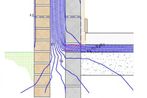
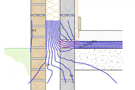
BBA tests (to BS-EN ISO10211) using one Accredited Construction Detail determined the ψ value of the floor/wall junction with two types of block; a) cellular concrete block inner wall and b) dense concrete block inner wall both with Thermoblock at the wall/floor junction.
The following isotherms show the heat flow using Thermoblock in both these standard scenarios. Since the isotherms are virtually flat, this implies that the heat flow is virtually vertical. i.e. in the direction of the supporting columns in the Thermoblock. The red rectangle represents the Thermoblock in a wall with dense concrete block (top diagram) and with an aerated concrete block (bottom diagram).
Offsetting the Cost
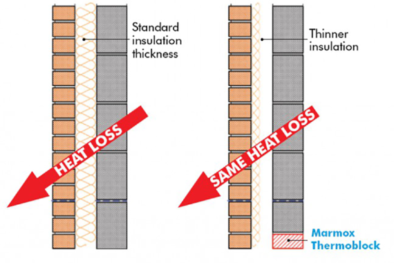
Using high insulating, load-bearing, building blocks such as Thermoblock could even allow the level of insulation required elsewhere to be reduced. Incorporating Thermoblock into a design will reduce the Y Value used in SAP or SBEM. Because SAP/ SBEM are concerned with the overall heat loss, if the Y value is reduced (meaning the heat loss at the thermal bridge is reduced), possibly the U value of the wall or floor insulation could be made a little bit worse yet still the overall heat loss or DER (Dwelling Efficiency Rate) would be the same.
For example:
- Standard thickness wall insulation with no thermal bridging block 100W/K + 12W/K = 112W/K
- If the heat loss at the thermal bridge is reduced to 2W/K, the thickness of the wall insulation could be reduced
- Slightly thinner wall insulation (cheaper) with thermal bridge insulation 110W/K + 2W/K = 112W/K
- The overall heat loss through these two walls could be the same……
With the need to improve the energy efficiency, and move closer towards the target of zero carbon homes, house builders and developers will continue to face the challenge of controlling heat losses due to thermal bridging. Finding smarter ways of insulating our homes using high insulating building blocks to reduce heat loss at the wall-floor junction is estimated can reduce this from the stated research levels of 30% to approximately 2%, and reduce the daily CO2 emissions associated with this wasted heat from 1.5kg to 0.1kg.
Marmox Thermoblock – Thermal Bridging Resolved
- Low Thermal Conductivity 0.047W/mK
- Guaranteed Low Ψ Values (part of bre’s certified thermal products scheme)
- High load-bearing strength (9N/mm2)
- Use at the wall-floor junction
- Replaces brick or block layer
- Unaffected by moisture
For more information on thermal bridging, see our page here.